Explainer 01
How electricity reaches your home
A plain-language guide to volts, amps, transformers, overhead and underground service, two-panel homes, solar, and battery backup.
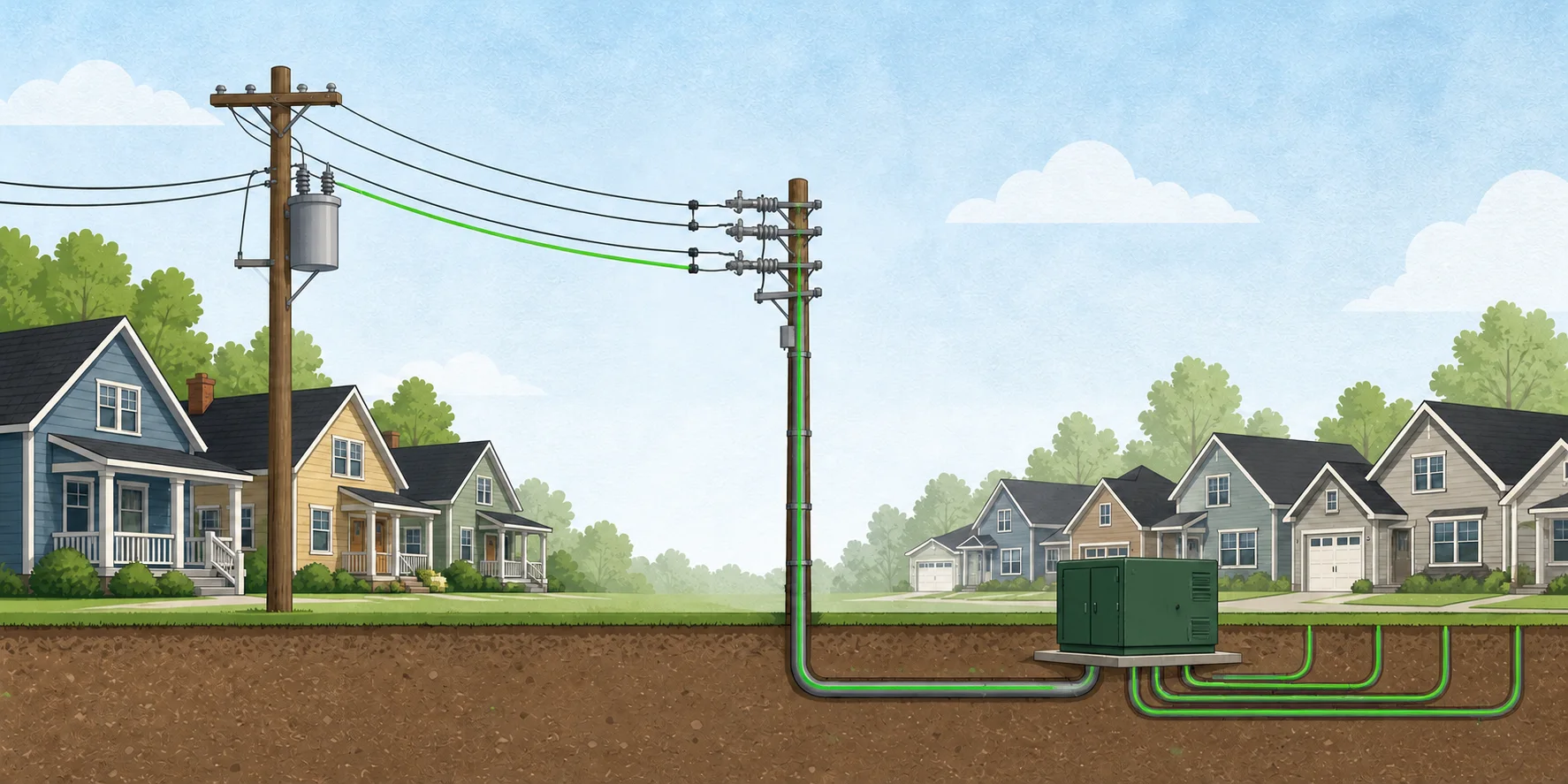
- Utilities use high voltage because it carries the same power with less current and less heat loss.
- A transformer near the homes lowers that voltage to the 120/240 volts used by most U.S. houses.
- One street can have overhead service on one side and buried service on the other.
- One transformer can serve several homes because the homes do not all use their full electrical capacity at once.
- A large 120/240-volt service can divide into two 200-amp paths. Each path carries L1, L2, and neutral, so both panels can supply 120-volt and 240-volt circuits.
- The Tesla design shown here uses one Gateway and one Powerwall 3 on each path. During an outage, they form two separate backed-up systems.
Start with four measurements
Electricity needs a complete circuit. There must be a path to a device and a path back. When the path is complete, electrical energy can heat an oven, turn a motor, or light a bulb.
A water-pipe comparison is useful as a starting point:
V
Voltage is the push
Volts measure the electrical difference between two points. Think of water pressure. Voltage can be present even when no current is moving.
A
Current is the flow
Amps measure how much electric charge passes a point each second. A device draws current when it runs.
W
Power is the rate
Watts measure how quickly a device uses energy. A 1,500-watt heater uses energy faster than a 10-watt bulb.
kWh
Energy adds up over time
Kilowatt-hours measure total energy use. A 1-kilowatt device running for 2 hours uses 2 kWh.
For a simple load, these measurements are related:
This relationship explains why power lines use high voltage. For the same power, higher voltage allows lower current. Lower current produces less heat in the wires, so power can travel farther with less loss.
What actually moves through the wire?
The wires already contain mobile electrons. With alternating current, those electrons mostly move back and forth. Electrical energy moves through the connected circuit very quickly. It is not a batch of electrons traveling all the way from a power plant to a toaster.
From the grid to a neighborhood
The grid is a connected system. It includes generators, transformers, transmission lines, substations, distribution lines, switches, fuses, and meters.
01
Generation
Power plants and other sources put energy onto the grid.
02
Transmission
Very high voltage carries large amounts of power over long distances.
03
Substation
Transformers lower the voltage for local distribution.
04
Distribution
Local feeders still operate at thousands of volts.
05
Home service
A nearby transformer supplies 120/240-volt service to homes.
Large lines on steel towers are usually transmission lines. The highest electric wires on ordinary wooden poles are usually distribution lines. Both normally operate far above household voltage.
Why are there often three high wires?
Many utility feeders use three-phase power. The system has three alternating voltages whose cycles are offset in time. This moves power smoothly and lets the utility spread customers across phases A, B, and C.
Three high wires on a pole may be the three phases, but appearance alone cannot confirm what a wire does. A typical detached house does not receive all three phases. Its transformer usually supplies single-phase, split-phase power instead.
Two routes through a neighborhood
Overhead and underground systems do the same jobs. One street can use both. Older homes on one side can receive overhead service while a newer group of eight homes on the other side receives buried service.
Older side: overhead
- Distribution wires run on poles.
- A transformer on a pole lowers the voltage.
- A service drop runs through the air to the house.
- The service connects to the meter and main panel.
The wire entering the house is on the low-voltage side of the transformer. It is not the same high-voltage wire at the top of the pole.
Newer side: underground
- A protected branch leaves a distribution feeder.
- An insulated primary cable assembly runs underground.
- A transformer in a green cabinet lowers the voltage.
- Buried service cables continue to home meters.
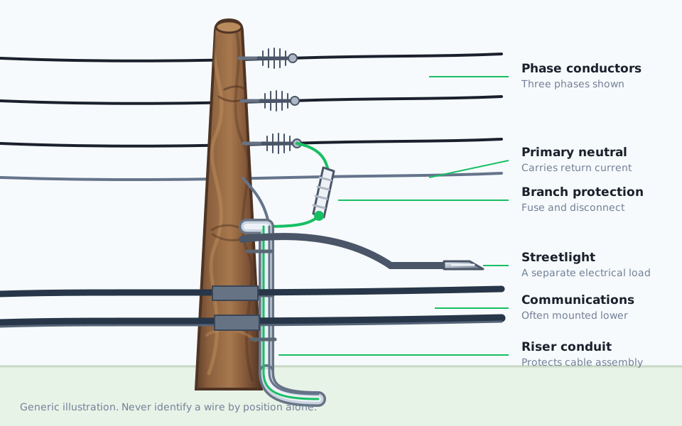
A gray riser on a pole protects the cable between the overhead line and the ground. The pipe itself does not carry electricity.
Overhead equipment is easier to see and reach, but it is exposed to trees, wind, ice, and vehicles. Underground equipment is protected from many of those hazards, but digging can damage it and repairs may take longer to locate. A pad-mounted transformer stays above ground so crews can reach it.
An 8-home underground example
A single-phase branch can leave the overhead feeder, run down the pole, go underground to a pad-mounted transformer, then continue through buried service cables to eight homes.
- 1. FeederThe main route may carry all three utility phases along the street.
- 2. Tap and riserProtection hardware connects one phase and the primary neutral to an underground cable assembly. The assembly enters protective conduit.
- 3. TransformerThe green cabinet changes distribution voltage to residential 120/240 volts.
- 4. Home servicesBuried secondary cables and junctions connect the transformer to eight meters.
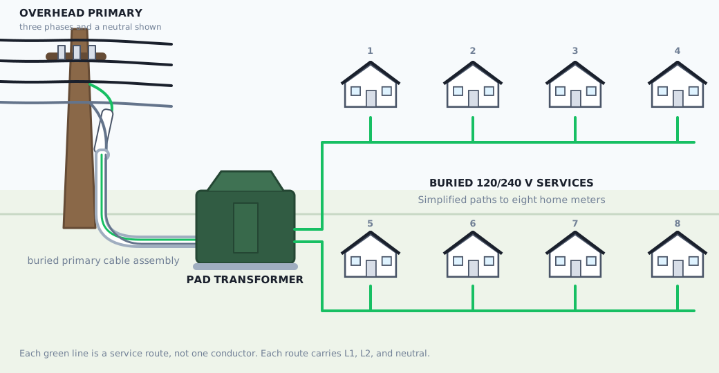
How can one primary branch serve eight houses?
The underground primary cable assembly carries a phase conductor and a neutral return path to the transformer. Some cable designs place neutral wires around the insulated phase conductor. The exact construction varies. Because this branch operates at high voltage, it can carry the same power with less current.
Suppose the eight homes together use 100,000 watts at one moment. This simplified comparison ignores losses and AC power factor:
On the 240 V secondary side
100,000 W ÷ 240 V ≈ 417 A
On an example 7,200 V primary
100,000 W ÷ 7,200 V ≈ 14 A
The 7,200-volt value shows the ratio. If voltage rises by 30 times, current for the same power falls to about one-thirtieth. Actual distribution voltage varies.
Utilities also account for load diversity. Eight homes do not use their full service capacity at the same time. A main breaker rating is a limit, not a measure of normal use. The utility sizes cables and transformers for expected simultaneous demand, engineering limits, and future growth.
What arrives inside a home
A typical U.S. home receives 120/240-volt, single-phase, three-wire service from a center-tapped transformer. The three wires are hot L1, neutral, and hot L2.
Swipe to follow the wires →
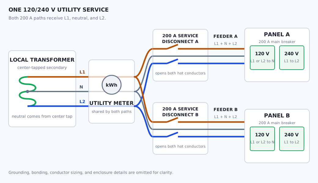
- Hot L1 to neutral = 120 volts. Most lights and ordinary outlets use this.
- Hot L2 to neutral = 120 volts. Other 120-volt circuits use this leg so the load can be balanced.
- Hot L1 to hot L2 = 240 volts. An electric range, dryer, HVAC system, or EV charger may use both legs.
- The equipment grounding conductor is a separate safety path inside the building. It normally carries no current.
What do two panels with 200-amp mains mean?
The service divides into two 200-amp paths, each ending at a panel protected by a 200-amp main breaker. Both paths carry L1, L2, and neutral, so each panel can supply 120-volt and 240-volt circuits.
People often call this a 400-amp service. A common version uses Class 320 metering, which is rated for 320 amps of continuous load, with two 200-amp main paths. It is not one 400-amp wire and not one path for each hot leg. Equipment labels give the exact ratings.
The names change at the first service disconnect. Conductors from the utility through the meter to that disconnect are service conductors. Conductors after the disconnect that supply a panel are feeders. A disconnect and panel can also be combined in one enclosure.
The homes in this 8-home example use this two-panel layout.
Normal utility power and Tesla backup
Without solar or batteries
Service conductors run through the meter to two 200-amp service disconnects. After each disconnect, a feeder supplies its panel. Panel A and Panel B each receive L1, L2, and neutral. Some homes combine a disconnect and panel in one enclosure.
With solar, Powerwalls, and Gateways
The design adds one Tesla backup system to each 200-amp path:
Swipe to follow both paths →
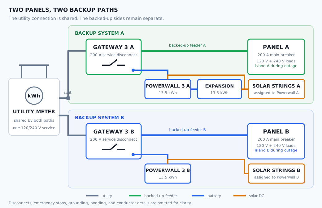
Each Gateway 3 is the 200-amp service disconnect for one path. A feeder runs from that Gateway to its panel. Each Powerwall 3 connects on the backed-up side of its Gateway and accepts DC power from its assigned solar strings. The design has two Powerwall 3 units plus one 13.5 kWh Expansion, for 40.5 kWh of nominal storage.
When the grid is working, utility power, solar power, and battery power can serve the panel on that path. Extra solar can charge its battery or flow to the grid when allowed.
When the grid fails, each Gateway opens its connection to the utility. Gateway A forms one backed-up island for Panel A. Gateway B forms another for Panel B. With enough sunlight and battery capacity, solar can power loads and recharge the battery on its own path.
The two backed-up sides do not combine. Powerwall A does not automatically power Panel B, and Powerwall B does not automatically power Panel A. This design keeps the two sides isolated, so it uses two Gateways and two Powerwall and solar paths.
Basic safety rules
Treat every overhead conductor, buried cable, transformer, pedestal, meter, and panel as energized unless the utility or a qualified electrician has made it safe. A wire's size, height, covering, or position cannot prove that it is harmless.
- Stay at least 10 feet from overhead power lines. Higher-voltage lines can require more distance.
- Never open, climb, sit on, or block a pad-mounted transformer.
- In the United States, contact 811 before digging and follow your state’s waiting and marking rules. Public utility marking may not include privately owned lines after a meter.
- Stay away from a fallen wire and anything it touches. Call 911 and the local electric utility.
- Do not open electrical equipment to learn how it works. Ask a licensed electrician to verify a home’s service.
Check your understanding
Sources
Equipment varies. Use utility records, equipment labels, and a licensed electrician to confirm a specific installation.
- U.S. Energy Information Administration: Delivery to consumers
- U.S. Energy Information Administration: Batteries, circuits, and transformers
- U.S. Energy Information Administration: Measuring electricity
- U.S. Department of Energy: United States Electricity Industry Primer
- U.S. Department of Energy: Electricity Distribution System Baseline Report
- U.S. Department of Energy: Transmission and distribution efficiency report
- PG&E: Electric and Gas Service Requirements
- Tesla: Powerwall 3 datasheet
- Tesla: Gateway 3 datasheet
- Tesla: Gateway 3 service connection
- Tesla: How Powerwall works
- OSHA: Electrical incidents and power-line safety
- U.S. Department of Transportation: Contact 811 before digging
Electricity needs a complete path
An electric circuit needs a complete loop: a path to a device and a path back. If that loop is broken, the device stops.
Three words to know
Higher voltage lets the utility move the same power with less current and less heat in the wires.
From the grid to a home
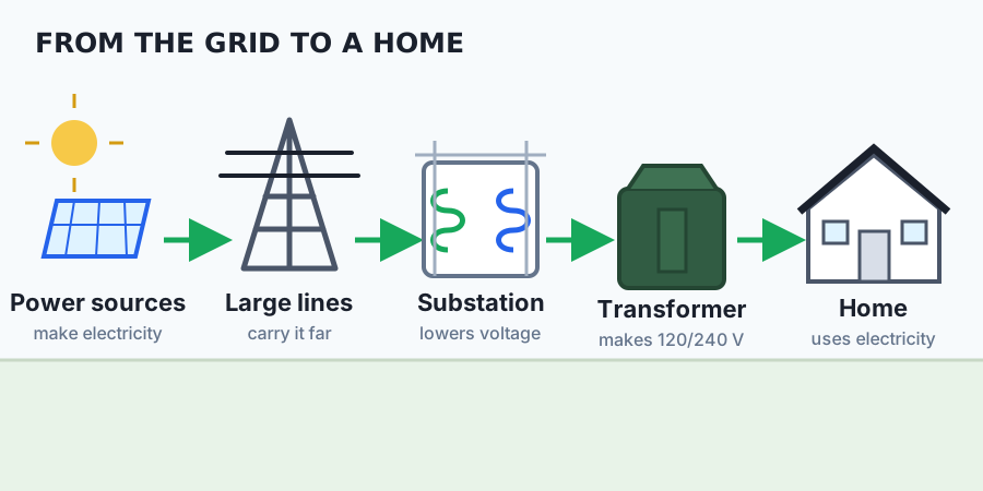
Transformers raise voltage for efficient travel and lower it in stages before electricity enters a home.
Two routes down a street
Overhead
The wires and equipment are easy to see.
Underground
Most of the wires are below the ground.
Both routes do the same job. One side of a street can use poles while the other side uses buried cable.
A home with two panels
120 V and 240 V Panel B
120 V and 240 V
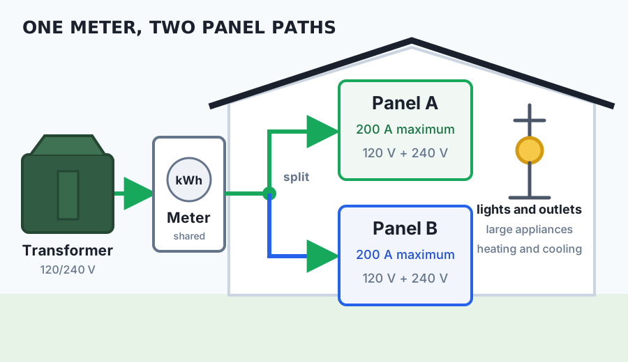
Each path can supply normal 120-volt circuits and larger 240-volt circuits. The 200-amp number is a limit. It is not the amount flowing all the time.
Solar and battery backup
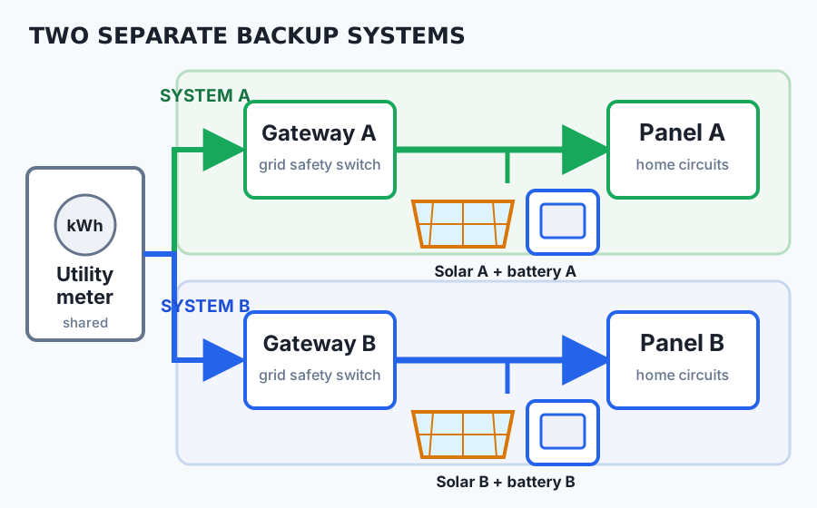
This two-panel design uses two separate backup systems. Each Gateway controls one panel.
During an outage, each Gateway disconnects its panel from the utility. Solar and its battery can keep serving that panel. System A and System B stay separate.
- Electricity needs a complete path.
- High voltage helps move power efficiently.
- A transformer lowers the voltage for homes.
- Overhead and underground wires do the same job.
- Two backed-up panels use two separate backup paths here.
Never touch, open, or climb electrical equipment. Stay at least 10 feet from overhead wires. In the United States, contact 811 before digging.